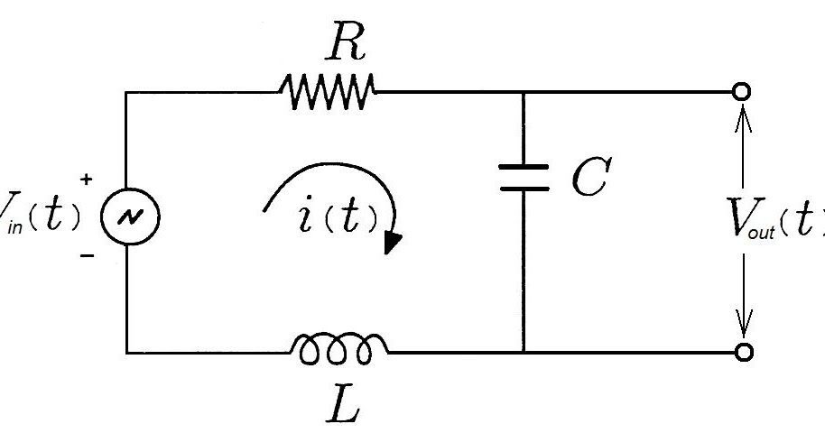

For small deviation in frequencies from center frequency, the input impedance is (6) For, is approximated as, (7) The magnitude transfer function of series rlc circuit is, (8) Design of RLC-Band pass fllters WS2010/11 E. An RLC circuit is called a second-order circuit as any voltage or current in the circuit can be described by a second-order differential equation for circuit analysis.

Today I am going to make a brief description of the step response of a RLC series circuit. Model a mechanical (masses, dampers and springs) and electrical system (inductors, resistors, capacitors) in the form of a transfer function. Find the component values R, L, and C after the frequency scale and the magnitude scale. For circuits (a) through (d) in Figure 8 – 2, use C = 0. To understand why, one constructs the transfer function for the circuit. The magnitude of the transfer function is minimum.The most important system functions in the time domain are:
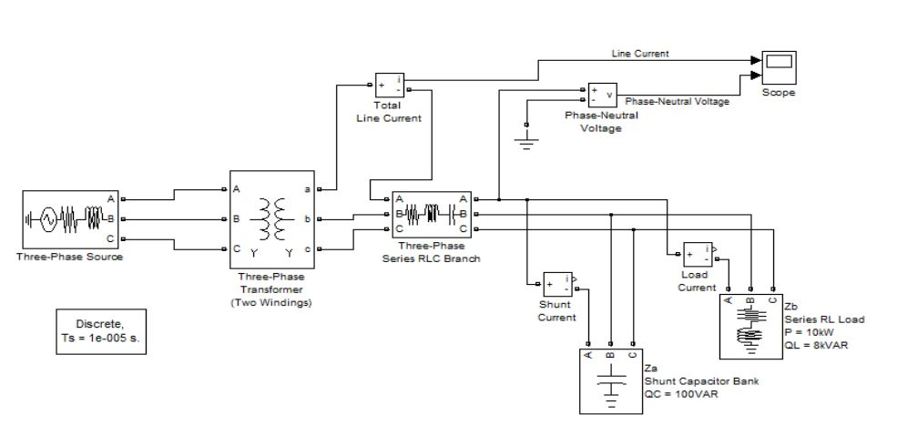
#Rlc circuit in matlab simulink generator
How do you find the cutoff frequency of a … The Maximum Power Transfer from a Power Supply to a Load Resistor Consider a power supply connected to a load resistor as indicated by the diagram below: The signal generator has an internal resistance as indicated and this is an intrinsic part of the power supply. Learn about the concept of the transfer function in signal processing, and how a transfer function describes a network. The response of the filter is displayed on graphs, showing Bode diagram, Nyquist diagram, Impulse response and Step An alternative to the intregro-differential equation model of a dynamic system is the transfer function. 3 Frequency Spectra of Real Signals 11:42. Using the knowledge gained previously, the transfer function can easily be found. Transfer Function of a RLC circuit 2 loop. The response of the filter is displayed on graphs, showing Bode diagram, Nyquist diagram, Impulse response and Step Derive the operation transfer function and the siunsoidal transfer function for an RC high-pass filter.

Use tf to specify the circuit's transfer function for the values. I was studying RLC Filters when I came across an RLC Parallel Circuit, in which the input is a current source, and the output is the voltage drop across the elements. The transfer function are given as V out(s) V in(s) = 198025 s2 +455s+198025 V o u t ( s) V i n ( s) = 198025 s 2 + 455 s Analyzing the Frequency Response of the Circuit. how i can get a Transfer Function of a RLC circuit 2 loop if i want the output current Obtain the transfer function Vo/Vs of the RL circuit shown below, assuming v s = V mcosωt. e X L = X C then circuit will behave as purely resistive circuit. () 0 i Vs Hs Vs = ()0 i Vj Hj Vj ω ω ω = Using sinusoidal source, the transfer function will be the magnitude and phase of output voltage to the magnitude and phase of input voltage of a circuit. These types of circuits are also called as RC filters or RC networks since they are most commonly used in filtering applications. Frequency Response of a Circuit ω 012= ωω cc Three important parameters Band-Pass Filter Center frequency (or resonance frequency), ω 0 is defined as the frequency for which a the transfer function of a circuit is purely real Bandwidth, βis the width of the passband Qualty factor is the ration of the center frequency ω 0 to the bandwidth For that I would like to have a 4th order transfer function of RLC circuit. Transfer function for rlc circuit Transfer function and state space model are developed for a circuit with resistor, inductor and capacitor in series as shown below.


 0 kommentar(er)
